Wednesday, October 13, 2010

Rationale Report

The three alternative solutions will each have to accomplish the same set of tasks provided by the MATE ROV competition. The solutions use different power sources to open and close the mechanical claw.  In addition, they utilize different claw designs to accomplish the tasks. As a result, there are pros and cons pertaining to the design of each solution.
Alternative solution one utilizes an electric motor to power the gears that will open and close the claw. The ratio of the gears on both sides of the big gear will be the same, so the claw will open and close at the same speed. A spindle gear will also be attached directly to the motor to slow it down to an appropriate speed. The claw will be designed with 2 segments: 1 pronged claw on the bottom and 1 rectangular-shaped claw on top. The pro of solution one is that the idler gears will work efficient and slow enough to maneuver the claw in a controlled manner. The cons of solution one are the gear cage and the claw design. The gear cage will obviously have to be taken into account when performing buoyancy calculations and trying to fit all components on the claw, however, it will consume a large percentage of the claw. The claw design will be able to complete all the tasks required, however, it will not be as effective as other solutions with resurrecting the PVC structure.
Solution two also utilizes an electric motor to power the idler gears on the mechanical claw. The ratio of the gears will be different on each side of the 1” big gear, so it will close at a faster rate then it will open. One 1/8” gear will be on one side and two 1/2” gears will be located on the other. The claw will be designed with two circular cups with rubberized ends that will come together to form a complete seal. One pro of solution two is that the fulcrum will be constructed distant enough from the half-circular cups so that it will be more efficient at performing the tasks that require picking up samples compared to the other solutions. Solution two will have the best control of the crustacean sample, bacteria sample, and entire claw. The con of solution two is that the claw design will weigh more than solution one.  
Solution three uses a different power source, which is a servo motor. It works differently from the electric motor utilized in the previous 2 alternative solutions in that it has limited range of motion and as a result, is not as powerful. A servo motor will be attached to the pivot point of the claw with a metal wire. The claw design for this solution will be the same as solution two, but smaller in size. One pro of solution three is less functioning parts than the electric motor. More parts to achieve the same goal creates more power, but also more friction. The con of solution three is the limited range of motion and less power.
Alternative Solutions
Solution
Solution 2
Solution 3
Ratings(1 to 10, 1 meaning poor, 10 meaning perfect)


The design must be operated remotely from a shack
10
-Easily accessible from a control shack
10
-Easily accessible from a control shack
10
-Easily accessible from a control shack
The mechanical arm must open to a minimum size of 3 inches
6
-Opens to over 3 inches
9
-Pivot point will allow it to open well wide enough
7
-Pivot point will allow it to open, servo limits the range of motion
The arm must collect samples of a crustacean species
9
-Pronged claw will be the best at picking up a crustacean
7
-Half circular cups may have issues
7
-Half circular cups may have issues
The arm must collect samples of a bacteria mat
7
-Claw design will collect bacteria samples.
8
-Claw design will be the best at picking up picking up samples
8
-Claw design will scoop up the samples
The mechanical arm must sample a vent site
7
-Pronged claws will most effectively take a sample
6
-Half circular cups might be limited in taking a sample
6
- Half circular cups might be limited in taking a sample
The mechanical arm must resurrect a PVC structure
5
-Claw shape may not be able to grab hold of the structure
8
-Most effective at resurrecting Hugo
7
-Claw design power source may not have enough power
Total Score
44
48
45
                                                                                                                                                                                                                                                                                

Friday, October 1, 2010

Calendar

October Log

10/1/10
Today I began modifying the format of testing procedures and research/brainstorming. In addition, I added two pictures and removed one from the background section. I still have to upload scanned pictures of my three alternate solutions to my blog.

10/8/10
Today I finished editing my testing procedures. Everything up to and including alternative solutions is completed and on my blog. I’m still experiencing difficulties with uploading pictures and getting them on to my blog. In addition, my Google calendar has issues showing up on my blog. I’ll be more up to date when I finish my rationale.

10/13/10
Today I started my rationale for each solution. I finished the pros and cons for each alternative solution. The next step is to finish the design matrix aspect of my rationale and then complete developmental work for the design of the mechanical claw.

10/15/10
I finished my design matrix for the rationale. The solution that recieved the highest score on the design matrix was solution 2, meaning it compared the most favorably to the specifications. I still have to post the design matrix to my rationale and then i can draw a wire frame of my mechanical claw on AutoCad

10/20/10
I started my developmental work on AutoCad. I'm having trouble making a wire frame diagram of my mechanical claw because I have not used Autocad in some time.

10/22/10
I began working on my orthographic drawing on AutoCad. I'm struggling with the drawing because it has been a long time since I last used the program. I think I am going to do the exploded isometric and rendered isometric by hand.

10/27/10
My exploded view is coming along nicely, so i won't need to do it by hand. The exploded view has all of the parts, however, they are not displayed in an order where it is easy to see how they come together to form the final solution for the mechanical claw.


Wednesday, September 29, 2010

September Log

9/29/10

Today I completed the descriptive abstract for my three alternative solutions. The only piece missing from my blog are pictures of each solution to go with the abstract. My background information needs two more pictures and my individual and team testing procedures need to be refined.

Tuesday, September 28, 2010

Alternative Solutions

The alternative solutions cover  how to power the mechanical claw and the shape of the claw to accomplish the tasks of the MATE ROV competition. Three power resources taken into consideration when creating the alternative solutions were hydraulics, an electric motor, and a servo. In addition, the shape of the claw was designed to the tasks provided by the competition, specifically the tasks involved with collecting samples of crustacean species, bacteria mats and resurrecting Hugo's frame.

Alternative Solution #1


The first alternative solution utilizes an electric motor to power the mechanical claw open and closed. The motor directly connects to the idler gears, which are located inside a cage measuring 6" in length by 4" in width. The idler gears will have 2 gears on one side of the 1" big gear and 1 gear on the other. In this solution, the speed ratio that the mechanical claw will open and close will be the same because the two gears on the same side will measure 1/2" each, while the single gear on the opposite side will measure 1/4". A 1/8" spindle gear will connect to the motor before the 1" big gear to lower the ratio. The claw will be constructed in a shape that has a pronged segment on the bottom to pick up objects and a rectangular shaped segment on the top to lock the objects in place.

Alternative Solution #2


The second alternative solution also utilizes an electric motor to power the mechanical claw as it does in the first solution. The cage containing the gears will be a square measuring 4" on each side. A 1/8” spindle gear will connect directly to the motor, so it will spin at the same speed as the motor. A 1” big gear behind that will be used to lower the ratio to one that is slow enough to operate the claw effectively. A 1/8” gear will be on one side of the big gear and two 1/2” gears will be on the other, separated by the pivot point. The claw will close much faster than it will open because the ratios on each side are not the same. The mechanical claw will be 8” long and consist of two half-circular shaped cups that will come together. The size of each cup will be 4” in length and 2” in depth. The fulcrum of the claw will be constructed distant enough from the cups so that the objects will not be forced out in the opposite direction when being picked up. In addition, rubber will be inserted on the lip of each circular cup to add traction. 

Alternative #3

  The third alternative solution requires a servo for a power source to make the mechanical claw function. A servo is a specific type of motor that consumes little energy because of its size. Servos have built in control circuitry. In this solution, a servo will power the claw to close, which remains open during all other parts of the competition until needed. The servo motor will be attached to the pivot point of the claw with a metal wire. The claw on this solution will be the same design as solution 2, but smaller in length. The two segments from the pivot points to the circular cups will be 3” as opposed to 5”. The location of the fulcrum on the claw will be constructed at a distance far away enough from the cups so that objects will not be forced out the front when the two claws converge.

The three alternative solutions consist of two different power sources, which are the electric motor and the servo motor. Solution 1 and solution 2 have variations of gear sizes. As a result, solution 1 operates on an even gear ratio, while solution 2 closes faster than it will open. Despite using less power, solution 3 is also a viable option. It utilizes a servo motor to close a mechanical claw that is a scaled down version of the claw implemented in solution 2. Both types of mechanical claws used in the three alternative solutions were designed based on the principle of shoveling the objects.  

Sunday, September 26, 2010

Research and Brainstorming

The alternative solutions will reflect the aspects considered in the research and brainstorming stage. I will design and construct a mechanical arm to be placed on the design structure of the remotely operated vehicle that a team member can operate efficiently. One important aspect to consider is the type of material used to construct the mechanical claw. Some of the types of material used on current ROV mechanical claws include plastic and metal materials. In addition, another important aspect to consider is the function that will power the mechanical claw to operate effectively.
Type of Material-

PVC Plastic Material:
Pros:
-Cheap
-Lightweight
-Durable
Con:
-Difficult to find in shape to construct claw

Metal Aluminum Material:
Pros:
-Durable
-Commonly used to construct claw
Cons:
-Costly
-Heavy

Type of power-

Electric Motor:
Pros:
-Effectively maneuvers in all directions
-Powerful
-Easily found
Cons:
-Heavy
-Cage for gears consumes space

            Servo-

            Pros:

            -Lightweight

            -Consumes little area

            Cons:

            -Limited range of motion

            -Small power source

Thursday, September 16, 2010

Testing Procedure

Testing Procedures

The final solution for both the mechanical claw and the ROV will function efficiently and be able to perform all tasks provided by the MATE ROV competition. The final solution will be able to collect samples of a crustacean species, collect samples of a bacteria mat, sample a vent site, and resurrect a PVC structure on the bottom of the testing pool. The hull will be able to fit all other components of ROV including the mechanical claw, propulsion, and camera. The hull will be constructed so it has the ability to maneuver efficiently allowing for all components to complete the tasks in the competition. The electrical system will power the ROV to maneuver effectively in the x, y, and z planes of the testing pool. The mechanical claw will be utilized in almost all tasks of the competition, specifically collecting samples of a crustacean species, bacteria mat, and resurrecting “Hugo”. The testing of the final solution will be administered by one team member who will control all functions of the ROV.
There are four types of tests to investigate the effectiveness of the final ROV solution. The first is an exploratory test, which is implemented prior to design solutions of the ROV. During this testing stage, the team designing the vehicle will understand the concepts related to the MATE competition, such as rules and regulations and tasks they must complete. The exploratory stage will iron out all kinks so the design solutions for the vehicle are within the confines of the competition and most importantly, will work if constructed properly.
Test that:
1. The idlers gears on the mechanical claw works properly
2. The power source for the mechanical claw is geared down to a usable speed
3. The mechanical claw is waterproof
4. The two claws come together when operated
The second type of testing is the assessment stage. The assessment tests will answer questions concerning the usability of the concepts applied to the design solutions. These tests will ensure the design solutions can complete the tasks provided by the competition. For example, assessment tests for the mechanical claw will ensure the designs will be able to collect samples of a crustacean species and bacteria mat, sample a vent site, and resurrect a structure.
Test that:
1. The mechanical claw opens to a size sufficient enough to grasp samples of a crustcean species and bacteria mat.
2. The claw design can resurrect a PVC structure
Validation testing will follow next in the testing stages, but will occur after the product has been created. This will be the first time all components of the final solution is all together. The purpose of this stage is to ensure the final ROV does not have any issues with the functioning parts. Also, it will test that the ROV meets all specifications for each part and that it achieves all goals previously set prior to the construction.
Test that:
1. The electric motor on the mechanical claw powers the idler gears properly
2. The mechanical claw graps the sample of a crustacean species
3. The claw succesfully samples a bacteria mat/vent site
Comparison testing will be performed at many stages during the testing process. It will be used to compare various ideas on how to build a specific part of the ROV, the type of material used to construct, and the method or power source utilized to make a part function. For example, a design matrix is implemented in the alternative solutions to decide what solution compared the most favorably to the specifications.
The mechanical arm testing process will focus around the effectiveness of the claw design and the power source to manipulate the arm. The preliminary stages for testing the claw design will be performed when the ROV is stationary and the other functions on the hull are not being powered. The preliminary stage will test that the claw is secure to the hull and does not hinder the movement of the hull or any other parts on the ROV.
The secondary stages will test the usability of the mechanical claw. It will ensure that the entire claw is sealed and the section containing the power source is waterproof. The secondary stages will be performed by placing the mechanical claw in a container of water. The tertiary stages will test the effectiveness of the claw. The mechanical claw should open and close efficiently. This stage will be tested by placing the mechanical claw on the hull and then hooking up all electrical systems to the claw. The ROV will be placed in the water and the mechanical claw will pick up samples and resurrect a structure.

1. Does the mechanical claw prohibit the other functions on the ROV?
2. Is the mechanical claw secure to the hull?
3. Is the section around the servo/electric motor waterproof?
4. Is the gear ratio low enough to operate the claw effectively?
5. Does the mechanical arm close and re-open?
6. Does it open to a size of at least 3 inches?
7. Does it pick up a sample?
8. Does it resurrect a PVC structure?
9. Does it collect and move objects to the targeted area?


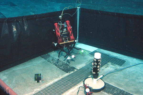
ROV in testing pool