Tuesday, March 29, 2011

MP3 FPU

The situation


Team Design Brief

            Design and construct a submersible remotely operated vehicle to achieve the tasks provided by the MATE ROV Competition that a team operator can use to simulate a real life ROV exploration in a chlorinated testing pool.   Each team member will individually design a different operating component of the remotely operated vehicle, which will include: propulsion systems, design structure, and a mechanical arm.

Individual Design Brief:
-Design and construct a mechanical arm to be placed on the structure of the remotely operated vehicle that a team member can operate efficiently. The mechanical arm must collect samples of a crustacean species and bacteria mat, sample a vent site, and resurrect a PVC structure.

Specifications:
-The design must be operated remotely from a shack.
-The design must be able to maneuver in any direction of the water column.
-The design must have a mechanical arm to pick up objects.
-The mechanical arm must open to a minimum size of 3 inches.
-The mechanical arm must collect samples of a crustacean species.
-The mechanical arm must collect samples of a bacteria mat.
-The mechanical arm must sample a vent site.
-The mechanical arm must resurrect a PVC structure also called "Hugo“.

Limitations:
-The design must operate at depths up to 4 meters.
-The design must be powered by a 12 volt 25 amp battery.
-The design must use nonpermeable water materials.


Developmental Drawings

MODEL-


TESTING-


ROV Hull Structure-


Current Final Product-


Friday, March 11, 2011

MP3 Logs

Jan 25 2011-

I have to gather the majority of my parts before I can start constructing my mechanical claw. I have purchased the gears at hobby masters. Also, I purchased 1/32" piano wire as a possible option for axels. I'm still thinking about using something more solid as axels.

Jan 27 2011-

Yesterday I purchased finishing screws as a more solid option for axels. However, with the size of these screws, I am forced to drill a larger hole in the center of the gear. I soon have to decide whether I want to apoxy or adhere the gears to the axels or use a stopper of some sort on the top and bottom of the gears.

Feb 1 2011-

Today I plan on looking for rubber stoppers at hobby masters or a department store. I recently found various size nylon stoppers that can be used to adjust the location of the gear of the axels inside my gear cage. I think this is a much better option than using a type of apoxy to adhere the gears because stoppers will give me room for error and everything does not have to be exact.

Feb 3 2011-

I have recently contacted a metal fabricating shop to weld my gear cage together. They suggested that instead of using aluminum sheet metal, I would need a thicker aluminum. This is because I plan on drilling through the top and bottom of the gear cage to insert the axels. It's called H & L Fabricators, located in Eatontown.

Feb 8 2011-

Over the last few days, I put in a call to H & L Fabricators and gave them the dimensions of the gear cage I would like them to weld. I picked it up and it looks great. I think there is a little too much extra space in the back of the gear cage, but it allows for changes if needed. I also had them cut the front and back sides of the cage, which allows water to flow through it. (Won't fill and add unnecessary weight to the ROV)

Feb 10 2011-

Today I layed out the gears and axels on top of the gear cage in order to finalize exactly where the parts will go. I took into account where the electric motor will attach to the last gear in the gear train. Theres about 2 to 3 inches of free space at the end of the gear cage, but after testing the weight of the aluminum gear cage, it does not weigh too much for the platform on the bottom of the hull. So, I will not remove the extra space on the gear cage.

Feb 15 2011-

I am currently looking for a lighter material to construct into the actual claw. Since the arms of the claw will be rotating on the gears, (instead of through the axels) the arm and claw should be as light as possible. This will decrease a large amount of unnecessary weight forced upon the gear as it is trying to rotate on the axel. At this point in time, I think i will use a lightweight plastic cup to construct the claw.

Feb 18 2011-

Within the next week, I should be making the axel holes on all the gears the same diameter as the finishing screws. I will soon as be drilling through the top and bottom of the gear cage. After that is complete, I will have to adjust the height of the gears with nylon plastic stoppers. On to the claw.

Feb 22 2011-

For the most part, I have the gear system complete inside of my gear cage. The only remaining step left to complete is to put all of the pieces of the claw together. Today I took some photos of my final gear cage design.

March 1 2011-

Today I am getting updated on paperwork. I'm creating my "senior project poster" to be displayed at an event that will show spectators what my ROV has been working on since September. It hits on some key points and parts of my senior project including design briefs, the design process, construction, and testing.

March 4 2011-

The completed ROV is due on the 21st of this month. That means that my mechanical claw should be done relatively soon, so I can mount it onto the hull of the ROV. Also, it needs to be completed prior to the 21st deadline so Matt can wire my claw to perform opening and closing movements. I'm helping Matt construct his controller before I finish the claw.

March 8 2011-

Today I am drilling the 3" machine screws (axels) through the gear cage. I am also modifying the 1" nylon plastic spacers to fit on the axels. I also have to purchase locking washers to go on the outside of the gear cage.

March 11 2011-

Wednesday, February 2, 2011

Plan of Procedure

Plan of Procedure


Supply List


Item
Description
QTY
Size
Remarks
1
Marine Epoxy
1
Tube
Seal Electrical Motor


Adhere Gears/Axels


Tools and Equipment List


Item
Description
Use


1
Band Saw
Cut Aluminum Sheet/PVC

2
Jig Saw
Slot Aluminum Sheet

3
Belt Sander
Form Final Claw


Materials List


Item
Description
QTY
Size
Remarks
                    1                                                         
PVC Pipe
1
3"
Cut into smaller pieces
                  2                               
Piano Wire
1
1/8”
Cut To Fit Gear Cage
                    3                      
Plastic Funnel
6
3”

                   4                         
Aluminum Sheet
             
         1
18”x18”

Drill holes-allow water flow


Parts List


Item [Drawing Designation]
Description
QTY
Size
Remarks
P 1
Claw
2
1.5"
Modified PVC pipe
P 2
Scoop
2
1.5”
Modified Plastic funnel
P 3
Axels
6
7"
Through Gear Cage
P 4
Gear Cage
1
6”x6”x6”
Perforated

Tuesday, February 1, 2011

STEMM REPORT

Matt Johnson

Systems Engineering II

Ms. Green & Mr. Cuttrell

17 January 2011

STEMM REPORT

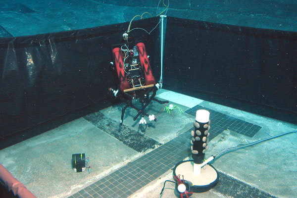
-The Capstone Design Project focuses on the main aspect of systems engineering- identifying a problem and then solving it. As part of the Capstone Design Project, I am designing and constructing a remotely operated vehicle with the aid of two team members. I am the mechanical engineer as I work alongside a structural and electrical engineer. The final solution is a remotely operated vehicle that will compete in the MATE ROV competition. The competition simulates a real-life remotely operated vehicle expedition off the coast of Hawaii. The MATE competition will be held in a chlorinated pool at Monmouth University. Maneuvering depths up to 4 meters, the final remotely operated vehicle will complete tasks specified by the competition. The tasks include collecting samples of a new crustacean species, sampling a vent site, taking temperatures at various locations in the pool, listening to sounds with a hydrophone, and resurrecting a PVC structure. The final solution is powered by a single 12 volt, 25 amp battery and is controlled by one team engineer from a control shack.
-As the mechanical engineer, I am designing and constructing a mechanical claw to be mounted on the hull of the remotely operated vehicle (see figure 1). The mechanical claw is used to complete specific tasks of the MATE competition, such as sampling a crustacean species and collecting a sample of agar. The final solution has a gear cage to power all functions of the mechanical claw. Inside of the gear cage, an 800 rpm electric motor powers the claw in both directions. A series of idler gears operates both sides of the 3” diameter PVC claw simultaneously.
ENGINEERING-
-The final mechanical claw solution is an innovation. The idea of a mechanical claw has existed for over a century. Other versions of the mechanical claw are used in various types of underwater vehicles, spacecrafts, and video games. The final claw solution is an adaptation of existing mechanical claws to best complete the tasks of the MATE competition. The final solution is innovated to fit on a smaller hull structure, operate within the parameters of the underwater pool environment, and run on a single 12 volt, 25 amp battery. It is a component of a closed system. The mechanical claw is a part of a final ROV solution that does not transfer mass between itself and its surroundings. However, the final ROV utilizes the mechanical claw component to move and lift objects in the chlorinated pool, outside of its hull structure.
-The type of engineering involved in the final solution of the mechanical claw is mechanical engineering. Mechanical engineering applies the principles of physics and material science for the design and manufacturing of the mechanical system. The final solution uses a series of gears to slow down the rpm’s of the PVC claw (see figure 2). The gear sizes progress from 10 teeth gears to 60 teeth gears, which ultimately power the claw component of the system in both horizontal directions.
MANUFACTURING-
-The type of manufacturing involved with the final design is flexible manufacturing. For many of the students taking part in the MATE ROV competition, it is their first time designing and constructing a product that will solve the problems the competition will impose. The Capstone Design Project is an educational experience, making it more likely that mistakes will be made. The purpose behind flexible manufacturing is to use materials and concepts that have the ability to adapt to unpredicted changes in the final design. The plastic gears, aluminum sheet metal, and 3” PVC piping are all mass produced materials that are gathered and constructed together to make the final mechanical claw.  The type of manufacturing involved with the materials selection of the final design is metalworking, plastic, and electronic manufacturing. Metalworking and plastic manufacturing are used to make aluminum sheet metal and PVC piping available to be utilized on the ROV. Electronic manufacturing is not only involved with operating the mechanical claw, but it is also used to power all the functions on the structure of the remotely operated vehicle.
SCIENTIFIC CONCEPTS-
-A major scientific concept that applies to the mechanical claw of the final design is gearing. They have been traced all the way back to the ancient Greeks, around 50 A.D. 
Gears work in tandem to change the speed and direction of a power source. Rotating teeth mesh together on a series of gears to create torque, or force that pushes or pulls an object. A small size gear (10 teeth) can interlock with a much larger gear (30 teeth) to create a mechanical advantage (Figure 3). The 10 tooth gear may be rotating at a faster rate, however, the 60 tooth gear will spin at a slower rate, while creating a sufficient amount of torque for the object it happens to be powering. On the other hand, gears can be utilized to speed up a power source by gearing up from a large gear to a smaller gear (Figure 4). Gears are a common component of systems because they can operate things much larger.
TECHNOLOGY-
-The technology involved with the final design of the mechanical claw is electric motors and gears. Electric motors (Figure 5) use electrical energy to create mechanical energy. The energy it transmits powers the first gear in the series of the final mechanical claw. The electric motor spins at about 800 revolutions per minute and uses a worm gear to rotate the first 30 tooth gear in the final solution. Gears are a scientific principle because they use force and torque to operate objects, but they are also a form of technology. Gears are considered simple machines because for the amount of distance covered by the rotating gears, they create a much greater output. They are used to operate large machinery in today’s world.
MATHEMATICAL CONCEPTS-
-A mechanical advantage will be created when using a series of gears to operate a mechanism. A mechanical advantage (Figure 6) multiplies the torque that the mechanical claw will exert. By utilizing the gears correctly in the final solution, small plastic gears are able to create a greater amount of torque to open and close the claw with sufficient force. A gear ratio is a mathematical concept that applies to the gear system inside of the gear cage. It is also concerned with the speed at which the claw ultimately opens and closes. The formula to calculate the gear ratio is as follows: number of teeth on the driver gear divided by the number of teeth on the gear that is being driven. Idler gears are a type of a gear series chained together between the first and last gear. Its purpose is to change the direction of the final gears. Therefore, it does not affect the gear ratio of the final mechanical claw solution. In the final solution, an 800 rpm motor will rotate a 30 tooth gear. The chain of 10 teeth idler gears will not change the gear ratio between the 30 tooth gear and the final 60 tooth gears. The final solution will rotate each claw simultaneously at 2 teeth per second.
CONCLUSION-
-The final design for the MATE ROV competition is an innovation of a mechanical claw. The final claw is adapted to a smaller scale hull and environment to best meet the tasks of the event. Flexible manufacturing is prominent in the design of the final solution, while mass production is heavily involved in the selection of the materials. The final design is powered by a series of gears inside of a cube shaped aluminum gear cage. The PVC claw will be attached to the gear cage, which will be mounted on the floor of the hull. The scientific and mathematical concept of gearing, along will the relationship between the gears, or gear ratio, was strongly taken into account when designing the final mechanical claw. The gearing system creates a mechanical advantage and torque to best operate the claw in both horizontal directions. The MATE remotely operated vehicle competition will require the structure, propulsion system, and claw mechanism to operate efficiently, as one system to complete the tasks the competition imposes.

Monday, January 3, 2011

Press Release

Capstone Design Project
305 MAST Way
Highlands, NJ  07732
Phone (732) 291-0095
Fax (732) 291-9367

Presentation Announcement
Contact: Matthew Johnson
Phone: (732) 671 4418
FOR IMMEDIATE RELEASE
9 A.M. EDT, April 5, 2011


Systems Engineering II: Robotics in the Classroom

On April 5, 2011 students from MAST (Marine Academy of Science and Technology), who have designed and constructed an underwater remotely operated vehicle over the past 9 months, will compete in the MATES ROV competition. The event will be held in a chlorinated pool at Monmouth University in Long Branch, New Jersey. Four teams comprised of three members have worked on their underwater ROVs as part of a Systems Engineering II course. The students will work to complete tasks provided by the MATES ROV competition in advance.

Matthew Johnson is a student at the Marine Academy who is competing with his team in the MATES ROV competition. He is specializing as the mechanical engineer while working alongside his team members Ross Basri and Matthew Gannon. As the mechanical engineer, he is designing and constructing a claw to perform the tasks provided by the competition. The team’s finished remotely operated vehicle will have a propulsion system (constructed by Matthew Gannon) to maneuver the vehicle and a hull (constructed by Ross Basri) that contains Matthew Johnson’s mechanical claw. The final product will operate in a chlorinated pool up to depths of 4 meters to complete the tasks specified by the MATES ROV competition.


CAPSTONE DESIGN PROJECT
The Capstone Design Project, as part of the Marine Academy’s Systems Engineering II course, will allow students to design and construct a product to solve a problem. The project is designed to simulate a problem that is occurring in the world today off the coast of Hawaii. To simulate how a team of engineers solve a real life problem, each ROV team is broken down into smaller parts that specialize in a particular aspect of engineering. Matthew Johnson has been given the role of the mechanical engineer, and as the mechanical engineer, he will work through the design process to create a final product to directly complete specific tasks. These tasks include resurrecting a PVC structure, sampling a bacteria mat, and collecting a crustacean species. His mechanical claw is operated by electric motors, which powers a series of gears to open and close the claw (see figure 1). The effectiveness of his mechanical claw will be dependent on the hull and electrical system of his teammates, which reflects how much of a team effort this project really is.


  (Figure 1)


MENTOR INVOLVEMENT
    While Matthew and his fellow classmates have been taking
Systems Engineering since their freshmen year at the Marine Academy, they are not quite experienced enough to go through the entire design and construction process alone. That is why each student doing the Capstone Design Project has at least one mentor. They can go to their mentors for references or advice at any point during the design or construction when they experience an issue. Matthew Johnson currently has one mentor, Martin Scott, who happens to be his uncle. Despite Mr. Scott not being a mechanical engineer, he is very useful with materials and robotics in general. Matthew has found him very helpful with the early stages in the design process, when he had an issue on how to collect the agar and what material to make the gear cage out of.

STEMM
The students at the Marine Academy will use knowledge of science, technology, engineering, manufacturing and mathematical concepts to design the most effective final product possible. Matthew Johnson, for example, has primarily used engineering concepts to design his mechanical claw. He has implemented complex machinery in powering his claw. Matthew’s claw will not have the ability to move up and down, however, it will use a spindle gear and an idler gear to open and close both claw’s at the same ratio.

Presentation
Like his fellow Systems Engineering II classmates, Matthew will soon give a formal progress update presentation to his class and instructors on the current status of his design. He will give a design brief of his overall project, and then dive into his final solution in detail. He will use isometric and orthographic CAD drawings to give a visual representation on how the final design will work and what materials he will have to use in the design process. Matthew will also talk about the current status of his construction and what the final mechanical claw will entail.


Expectations
All members of Matthew’s team will rely on one other for each aspect of the final remotely operated vehicle to successfully operate. The expectations for the mechanical claw (see figure 2) are to resurrect the PVC structure, sample a bacteria mat, and collect a new crustacean species. The expectations for the propulsion system and hull design will aid in the expectations for the final ROV that will compete at the MATES ROV event.


(Figure 2)

SUMMARY
  Students taking the Systems Engineering II course at the Marine Academy have a rigorous senior year with the Capstone Design Project. Each team will design and construct an ROV that will complete the tasks provided by the MATES ROV competition. It will be interesting to see the final products and how they fare at Monmouth University on April 5th.


For more details about ROV in Long Branch, New Jersey contact Matthew Johnson at MatthewJohnson@mast.mcvsd.org or visit MAST (Marine Academy of Science and Technology) at www.mast.mcvsd.org.


About the Marine Academy of Science and Technology
The Marine Academy of Science and Technology (MAST) is a co-ed four-year high school, grades 9-12; one of five career academies administered by the Monmouth County Vocational School District. The Marine Academy is fully accredited by the Middle States Association of Schools and Colleges and offers small classes with close personal attention. The Marine Academy was founded in 1981 as a part-time program, which has since grown to become a full-time diploma-granting program. The school's curriculum focuses on marine sciences and marine technology/engineering. The MAST program requires each student to participate in the Naval Junior Reserve Officer Training Corps (NJROTC) in lieu of Physical Education.
MAST is located in the Fort Hancock Historic Area at the tip of Sandy Hook, New Jersey. The school campus is located adjacent to the Sandy Hook Lighthouse, the oldest working lighthouse in the country, in thirteen newly renovated buildings, within walking distance of several beaches. The "Blue Sea" is a 65-foot research vessel owned and operated by the Marine Academy and berthed at the U.S. Coast Guard Station, Sandy Hook. The vessel is used in all facets of the program.
For additional information:
Marine Academy of Science and Technology
732-749-3360
Matthew Johnson, E: student@mast.mcvsd.org
Wendy Green, V: 732-291-0995